
It’s been about five years since I worked on this blog, that means there was A LOT of spam comments waiting for me. Thank goodness for anti-spam apps.
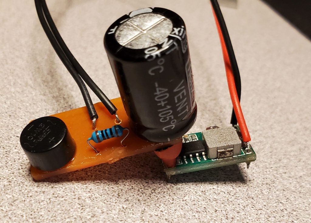
Recently I have been working on an electronic circuit to convert either DC or DCC track power to around 5 volts or so. At that voltage I can power LEDs, an Arduino Nano, or a bunch of other electronic devices. It uses a capacitor to store enough voltage to compensate for momentary flickers from dirty track or wheels. It was pretty similar to a lot of circuits out there.
My first design used a bridge rectifier feeding the DCC signal in and getting DC out. I was reading however, that they are not fast devices and can let negative voltage out of the positive lead as the polarity of the DCC changes. (DCC changes from positive to negative very quickly and it is the timing of these changes that is the “code” that a DCC device reads so it knows what to do). I found information that reverse voltage can damage the capacitor, but nothing that told me how much was safe. I can build a circuit from a schematic, and figure a little out, but i am not an electronics answer person.
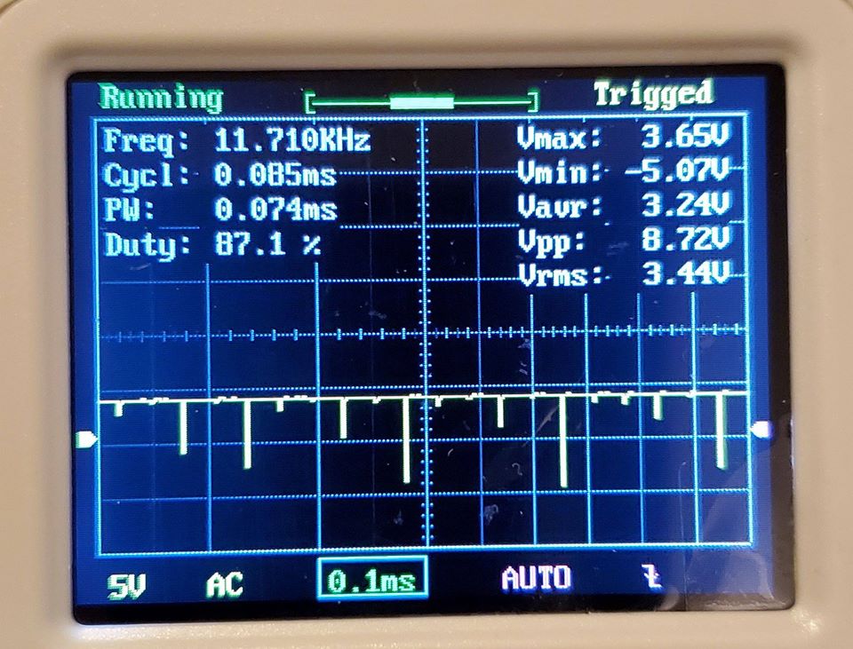
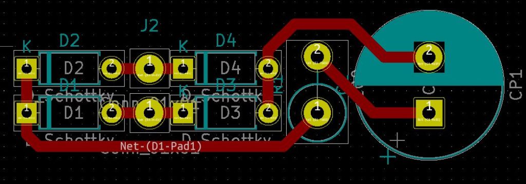
So I fired up my $20 oscilloscope and took a look at the voltage coming out of the bridge rectifier when i input DCC track voltage. Sure enough, there were negative spikes coming out of the positive leg of the rectifier. Why take a chance I thought. Since I am milling my own PCBs on a cheap chinese CNC mill (more on this later), some experiments were easy.
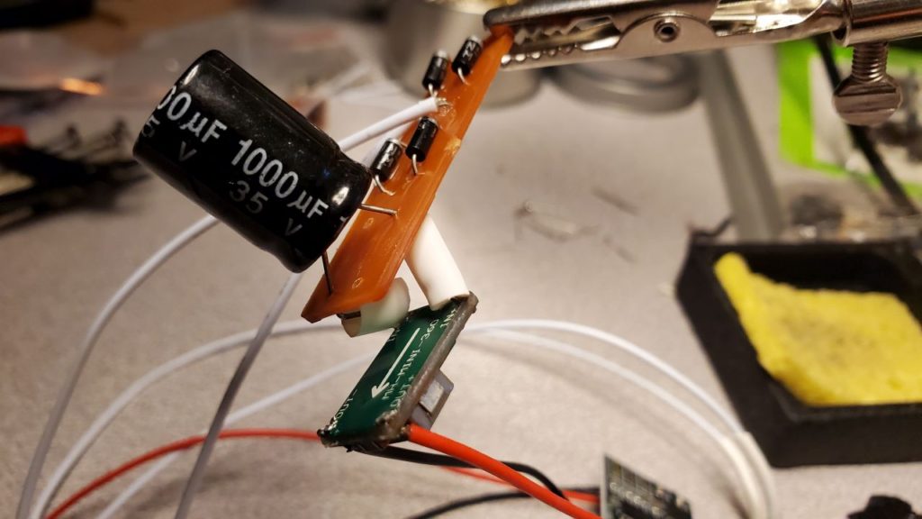
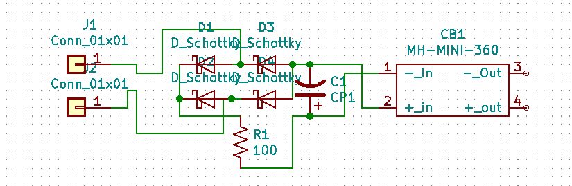
I designed a very simple board that had four schottky diodes instead of the bridge rectifier. I hooked the oscilloscope up to this circuit and there was absolutely no reverse spike- it was very smooth with these fast diodes doing the conversion. So, since these diodes are cheap, and do not take up much space, I can’t think of a reason not to use them instead of a bridge rectifier. Why take a chance? Of course, I am waiting for someone who knows about electronics to explain why I am wrong.
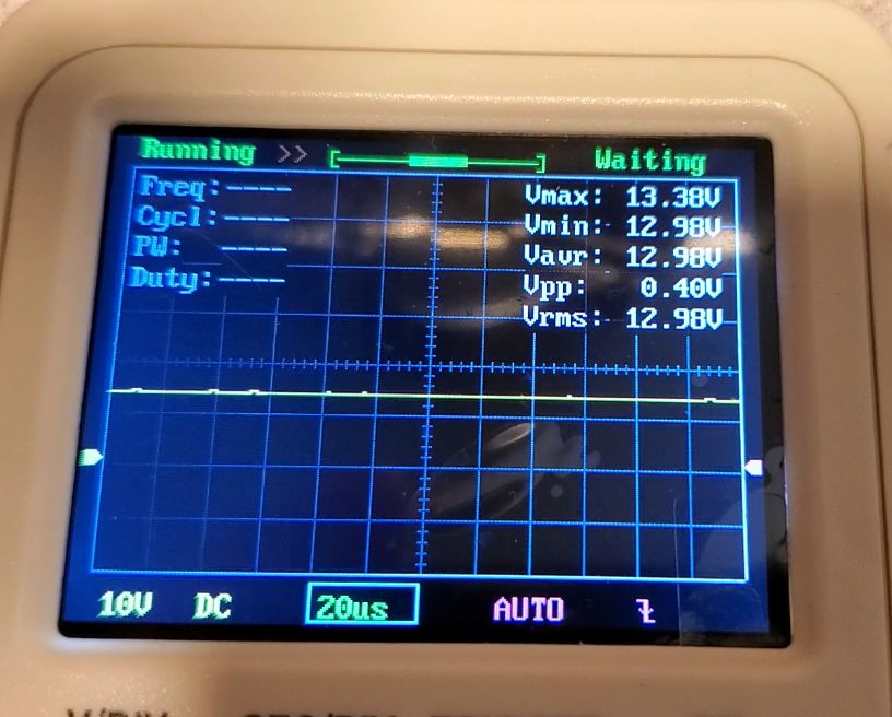
This is the scope of the output from the diodes, no negative spikes.
And the proof is in the pudding. Here it is hooked up to a cheap MP3 player feeding an IPhone 4 speaker running off DCC track power. And any sound effect can be installed on the memory card. It will keep going for about half a second after power is removed to compensate for dirty track or wheels. That could be increased with a bigger, or additional capacitor. Can anyone say cheap sound car?
This is the circuit diagram:
This is a diagram of the circuit layout:
The voltage converter is similar to these on amazon (
https://www.amazon.com/HiLetgo-Super-Converter-Module-Adjustable/dp/B00LODGDYE/ref=sr_1_40?dchild=1&keywords=dc-dc+buck+converter&qid=1598994185&sr=8-40 ), although I got the cheaper ones off aliexpress.
The MP3 player was from aliexpress, too:
https://www.aliexpress.com/item/4000188516180.html?spm=a2g0s.9042311.0.0.74f94c4dP7cx37