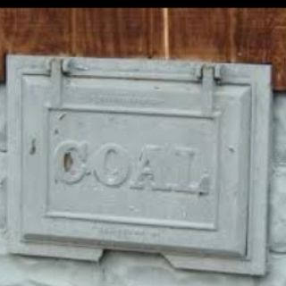
Years ago coal was delivered to many homes and businesses. A lot of times there was a metal door the coal delivery company would open and pour the coal through. Well, I was on facebook and someone asked in a model railroading group if anyone made a coal door as a detail part. I asked him what they looked like and what size they were, and not too much longer my Anycubic Photon was churning out the part.
Picture of the coal door requested
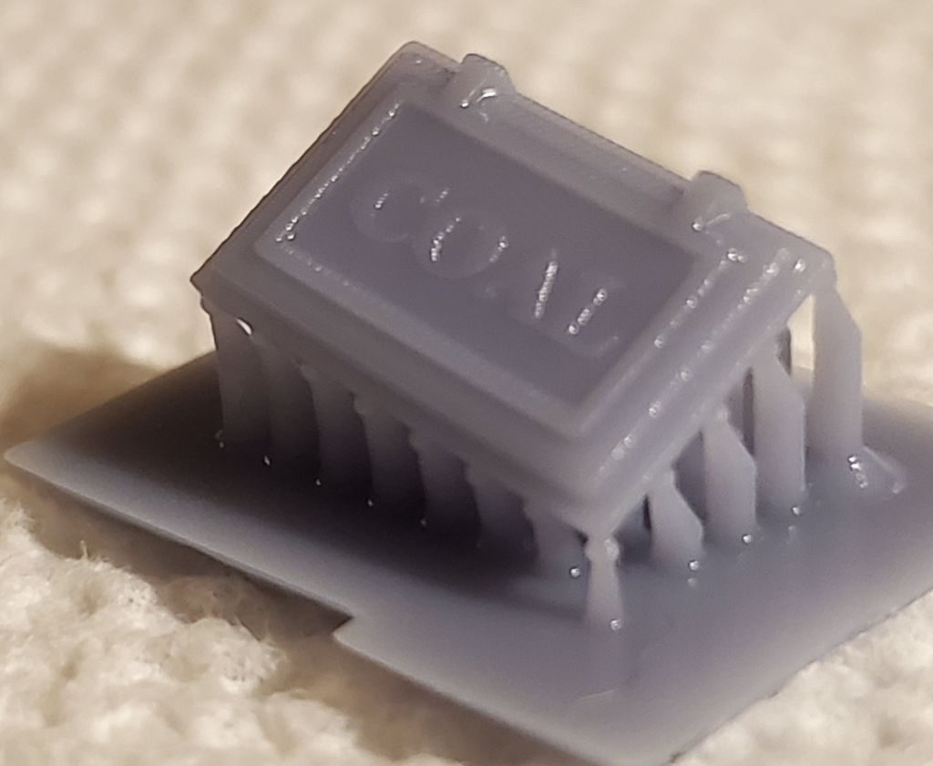
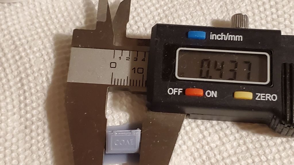
HO Scale coal door
It’s about 2 foot by 3 foot.
It wasn’t a complicated model. I designed it in sketchup, then scaled it, and sliced it in chitubox. A sped up screensave of the design process can be found on youtube.
It’s been about five years since I worked on this blog, that means there was A LOT of spam comments waiting for me. Thank goodness for anti-spam apps.
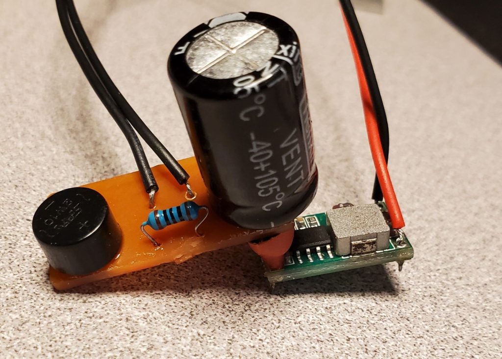
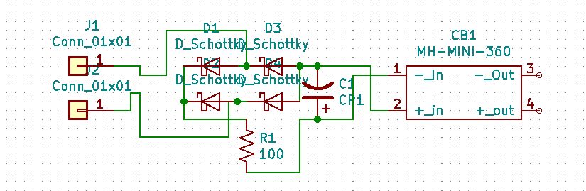
Recently I have been working on an electronic circuit to convert either DC or DCC track power to around 5 volts or so. At that voltage I can power LEDs, an Arduino Nano, or a bunch of other electronic devices. It uses a capacitor to store enough voltage to compensate for momentary flickers from dirty track or wheels. It was pretty similar to a lot of circuits out there.
My first design used a bridge rectifier feeding the DCC signal in and getting DC out. I was reading however, that they are not fast devices and can let negative voltage out of the positive lead as the polarity of the DCC changes. (DCC changes from positive to negative very quickly and it is the timing of these changes that is the “code” that a DCC device reads so it knows what to do). I found information that reverse voltage can damage the capacitor, but nothing that told me how much was safe. I can build a circuit from a schematic, and figure a little out, but i am not an electronics answer person.
This is my original design using a bridge rectifier feeding a buck dc-dc converter
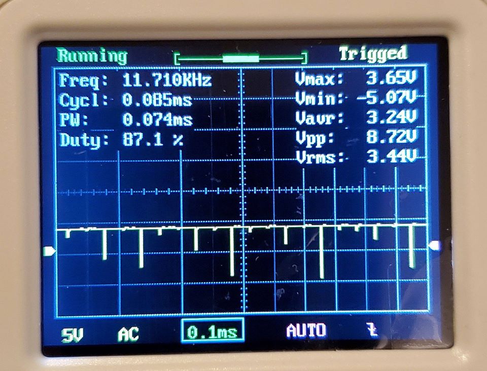
So I fired up my $20 oscilloscope and took a look at the voltage coming out of the bridge rectifier when i input DCC track voltage. Sure enough, there were negative spikes coming out of the positive leg of the rectifier. Why take a chance I thought. Since I am milling my own PCBs on a cheap chinese CNC mill (more on this later), some experiments were easy.
These are the negative spike coming out of the bridge rectifier when DCC track voltage is fed in. This is the feed to the capacitor.
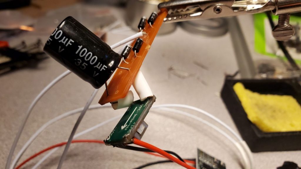
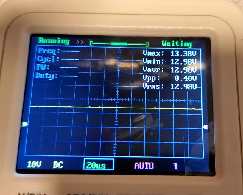
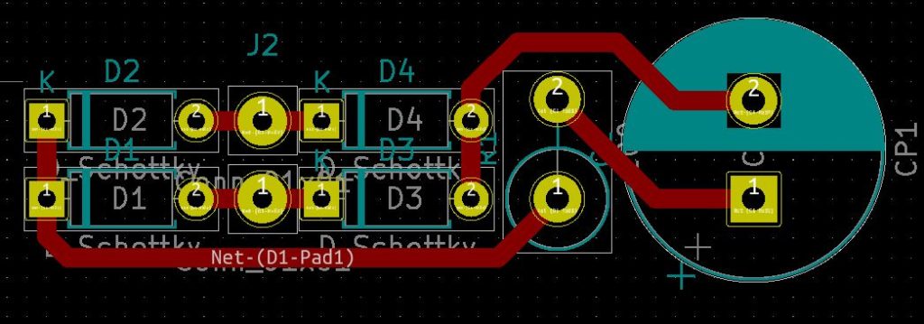
I designed a very simple board that had four schottky diodes instead of the bridge rectifier. I hooked the oscilloscope up to this circuit and there was absolutely no reverse spike- it was very smooth with these fast diodes doing the conversion. So, since these diodes are cheap, and do not take up much space, I can’t think of a reason not to use them instead of a bridge rectifier. Why take a chance? Of course, I am waiting for someone who knows about electronics to explain why I am wrong.
Here is the converter using the diodes This is the scope of the output from the diodes, no negative spikes.
And the proof is in the pudding. Here it is hooked up to a cheap MP3 player feeding an IPhone 4 speaker running off DCC track power. And any sound effect can be installed on the memory card. It will keep going for about half a second after power is removed to compensate for dirty track or wheels. That could be increased with a bigger, or additional capacitor. Can anyone say cheap sound car?
To understand what is possible with 3D printing you have to understand the limitations of the material you can print in. Shapeways was the company that printed my models, has guidelines for the minimum thickness for their different materials. The two I most commonly use are Strong and Flexible, which I’ll call “WSF” (White Strong Flexible) and Frosted Detail , which I’ll call “FUD” (Frosted Ultra Detail). Each of these materials has advantages and disadvantages, and the model you are making determines which material you want to use. Continue reading “How Small Can You Go? (#1 Start here)”
In the last post I talked about two material that can be used to print 3D models, WSF and FUD, and two features found on 3D models, Walls and Wires. There are three more concepts that you have to consider when designing a 3D model, Embossed Details, Engraved Details and Clearance between parts. Their names are fairly self explanatory. Continue reading “Embossed and Engraved Details (#2)”
I have found several software programs that I use to develop my models, but all my models start in Sketchup. Teaching someone to use Sketchup has already been done many times, and there is a thriving online community using the product.
The first this we have to do is add another pocket to the other side of the dumpster. It’s a simple matter of Control-C to copy and Control-V to paste it, then we drag it to the other side and rotate it 180 degrees. We can use a guide line to show the upper cornet of the pocket, then use the nudge tool to get it aligned just right.
You may have noticed we are designing this dumpster full scale. At the end of the process we will shrink it to 1/87th size. It’s much easier, avoids having to do a lot of math, and Sketchup was really intended for architects to do buildings. It doesn’t always like very small measurements.
Finally, a design issue! You may notice that many of the dumpsters have wear plates welded on in front of the pockets to protect the sides as the forks of the truck go in and out and so a fork doesn’t go through the front if the driver is a little off.
Is this the kind of detail an average user would notice? Probably not, but it does add to the model and is easy to do. Since it makes the wall thicker, not thinner, I can add it without worrying about breaking a design guideline, too.
I am not sure how thick the plates are, but this is a situation where if we stick to scale absolutely, the detail may not be noticeable on the model. But, a scale inch should be enough, and that’s how thick we will make them.
I just noticed the reinforcements by the wheels. Although I’m actually ahead of the blog in the design of the dumpster, I’ll have to remember to add them later.
I am looking at the corner of the wear bar. Sharp corners don’t survive well in real life, and often a slightly rounded corner looks better in my mind. I think we’ll round the vertical edge of the wear plate. There is an add-on for Sketchup called “Rounded Corners” of all things. it allows us to select the edges, the radius of the edge we want and then does all the hard work for use.
The last thing we’ll do on this post is make a wheel, copy it three more times, and put them in place. We will make each wheel a group (think sub-assembly) so later on we can delete them, or change them, without effecting the rest of the model. Suppose we want to make a version without wheels- we’ll have the basic dumpster and only have to make some small changes.
Because it will stick out Shapeways considers the wheels as wires, even though they’re not round. Because they are not supported on both ends, they’re unsupported wires. Back in post two I included a chart that shows the minimum diameter of a wire in the WSF material in HO Scale, which is 3.43 scale inches. That means no interior dimension can be less than 3.43 inches, and since we want this to print in the polished materials, we need it to be about 3.8 inches. 4 inches is safer though, and a half a scale inch more or less isn’t going to matter much to how the finished model looks.
I had to completely redo the wheels. The first time I made parts too thin. When I made them thick enough, the wheels didn’t look right. I started with wheels 6 inches in diameter, which was actually large than I wanted, but the second time I went up to 8 inches. These are bigger than the wheels I’ve seen in real life, but the proportions between the different parts looks better when they are made thick enough to meet the design criteria.
This video is a little longer, but again I have chopped out parts and sped it up between 2 and 4 times the actual speed.
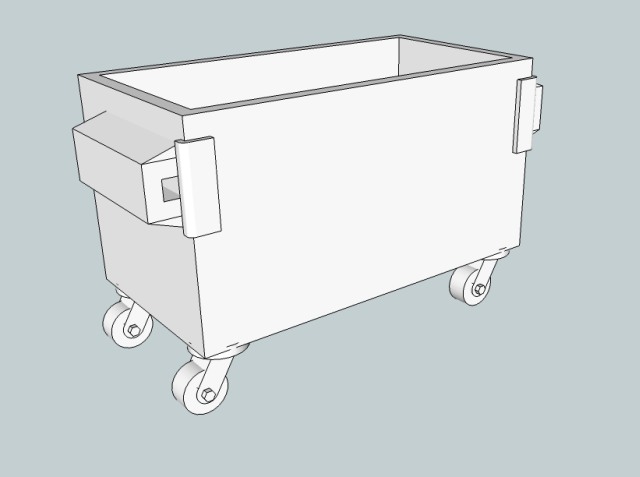
I think the base for our dumpster is almost done. We still need to add those reinforcements to the lower corners, then we’ll start on the lids.
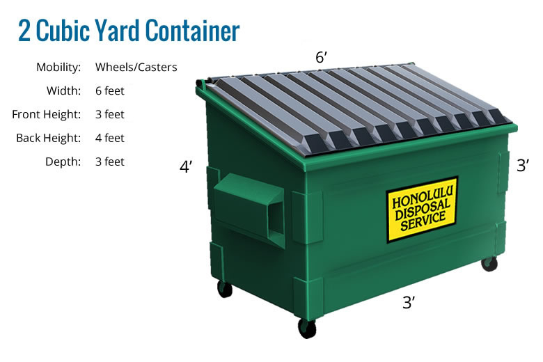
Here’s how the dumpster looks so far. If you compare it to a picture of an actual dumpster the wheels are too big, but printed in 1/87 they’ll look fine. Put behind a factory or store it’s a small detail that will add to the scene, not be the scene.